Physical Layer Improvements
Multiple-Input, Multiple-Output (MIMO)
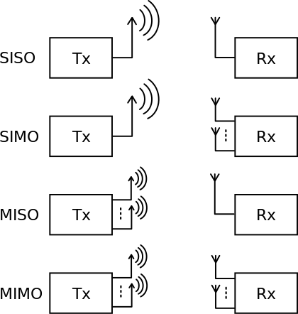
MIMO, which stands for Multiple-Input Multiple-Output, is the heart of 802.11n. The previous versions of IEEE used only one antenna. One for the reception device and another one ofor the emission device. This configuration is called SISO for Single-Input Single-Out. The compatibles devices with 802.11n are equipped with several antennas. At most four antennas.
Different technologies take advantage of MIMO. Among all of these, we will talk about Spatial Multiplexing (SP), Beamforming and Multiple-Ratio Combining (MRC).
Beamforming
The goal of beamforming is to improve the SNR (signal-to-noise ratio) on the receiver. This way we increase date rates and decrease retransmissions. It uses the principle of interference of waves. The two following figures show an example of interference. The left one shows what we call destructive interference. This happens when two waves (the green and blue ones), with a delay close to π, interfere. The red wave is the sum of the two previous sinus. The second figure shows the opposite effect, called constructive interference. In this case, the two interfering waves (the blue and the green ones) have almost the same phase.
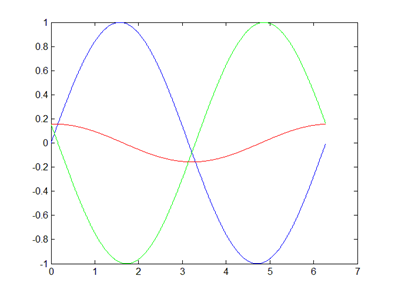
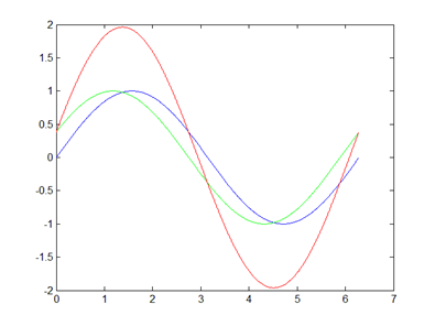
The green and the blue waves can be the signals sent by a AP (Access Point), equipped with to antennas, each antenna sending one of the two signals. We suppose that the signal is sent to a device equipped with only one antenna. The device receives the red signal, sum of the two issued signals. This way, the received signal can be as good as expected, absolutly null or twice better than expected.
So how does beamforming uses this phenomenon? It is performed by changing the phase of one of the two signals, so that the device is located in a region where the two wave interfere constructively. This way the signal strength can be twice better than the strength signal of the sent waves.
This technology has several constraints:
To know how to set the phases of the signals, the AP needs to know the strength of the received signal on the device. It supposes that the device sends this information to the AP. Sadly, only a 802.11n is able to do so. This way, beamforming is not compatible with previous versions such as 802.11a, b or g.
This technology is much more efficient when there are few obstructions or radio-reflective surfaces.
It is not possible to optimize the phase of the transmitted signals when sending broadcast or multicast transmissions.
Maximal-Ratio Combining (MRC)
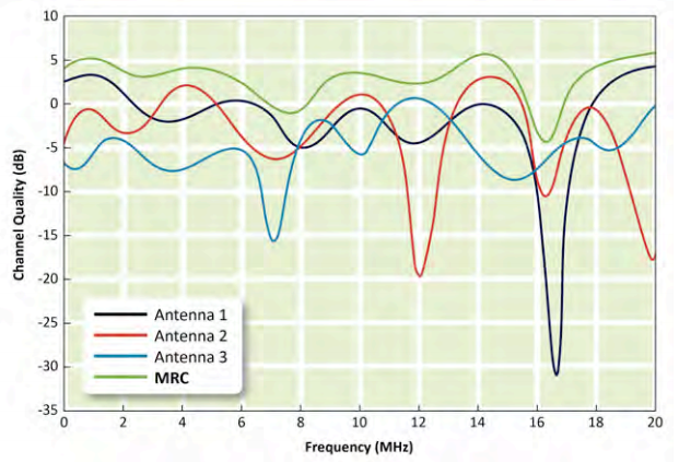
The MRC is an algorithm used at the level of the receiver. It takes advantage of the multiple antennas at the receiver. The signals received on the different antennas followed different paths. Therefore, the amplitude of the received frequencies varies. This algorithm analyses the different signals obtained and generate a new one, inspired by the best of every signals. On the following figure is shown the MRC signal generated, based on three other signals received by three different antennas.
Note that a 802.11n device can operate a MRC signal even if the transmitter is a 802.11a, b or g, thanks to spatial diversity (see below).
Spatial Multiplexing (SM)
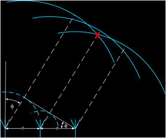
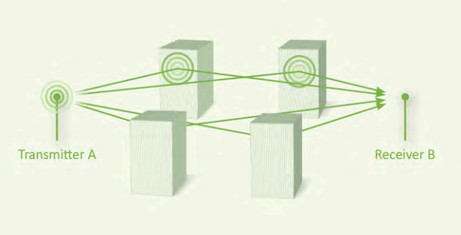
SM transmission technique relies on the phenomenon of multipath. This phenomenon happens in a non-ideal transmission case when the environment contains obstacles, wave reflectors. In this situation, the receiver might get a direct wave from the transmitter, but it will also get copies of the direct signal, results of one or more reflection on the environment. The following figure resumes this situation.
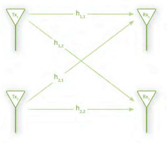
While this is often source of information loss in transmission technologies, 802.11n takes advantage of it thanks to the SM. It allows MIMO capable devices to send different signals at the very same time, using several equipped antennas. These different signals are called spatial streams. Each of the sent signals followed a slightly different path due to the short distance between the antennas. This is called special diversity. Each antennas of the receiver get a different signal. These signals are independently decoded and then combined to reassemble the date stream. The following figure summarize these explanations. A data h can be separated in h1 and h2. The data h1 is transmitted by the antenna Tx1 while at the same time, h2 is transmitted by the antenna Tx2. At the level of the receiver, both antenna Rx1 and Rx2 receive a combination a h1 and h2 but under a different signal.
This technology increases the SNR but also significantly data rates.
Radio Enhancements
Channel Bonding
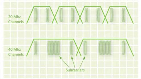
Channel bonding is used in 802.11n to bind two 20 MHz channels, to make one 40 MHz channel. Doubling the frequency space doubles the bandwidth, and doubling the bandwidth doubles the throughput. We can make an analogy with a highway. Moving from a two lines highway to a four lines highway doubles the traffic capacity. Same result applies in network. While 802.11a and g used 20 MHz channels, 802.11n uses 40MHz channels, thanks to Channel Bonding (see the following figure).
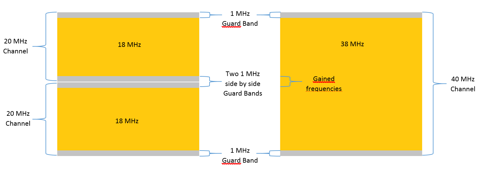
In fact, channel bounding more than doubles the throughput. One 20 MHz channel is composed of two 1 MHz channels, one at the beginning of the channel and one at the end, called Guard Bands. The 18 MHz left are used for data transfers. When using Channel Bonding, the two Guard Bands between two 20 MHz channels can now be used carry information.
HT-OFDM
802.11a and g used Orthogonal Frequency Division Multiplexing (OFDM) to transmit information. 802.11n continues to use OFDM but in a slightly different way. This new version is called HT-OFDM for High Throughput OFDM.
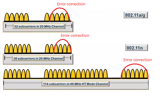
How does OFDM works? The OFDM divides a channel into several subcarriers to carry information. For example, 802.11a and g use an OFDM that divides the 20MHz channels into 52 subcarriers. 48 of those are used for data transmission and 4 others are used for forward error correction. This configuration offers a data rates of 54 Mbps at best.
When 802.11n uses 20MHz channels, HT-OFDM now offers 56 subcarriers. There are still 4 that are used for forward error correction and now 52 that are used for data transmission. This marginally increases the data rates to a maximum of 65 Mbps. This is when we use a single-transmitter radio. For two transmitters, the maximum data rates is 130 Mbps. Three transmitters provide a maximum data rates of 195 Mbps. The maximum four transmitters can deliver 260 Mbps.
When a 40MHz channel is used, we get 108 subcarriers to transmit data information and 6 subcarriers for forward error correction. This way the channel is divided into 114 subcarriers. This provides a maximum data rates of 135 Mbps, 270 Mbps, 405 Mbps, and 540 Mbps for one through four transmitters, respectively.
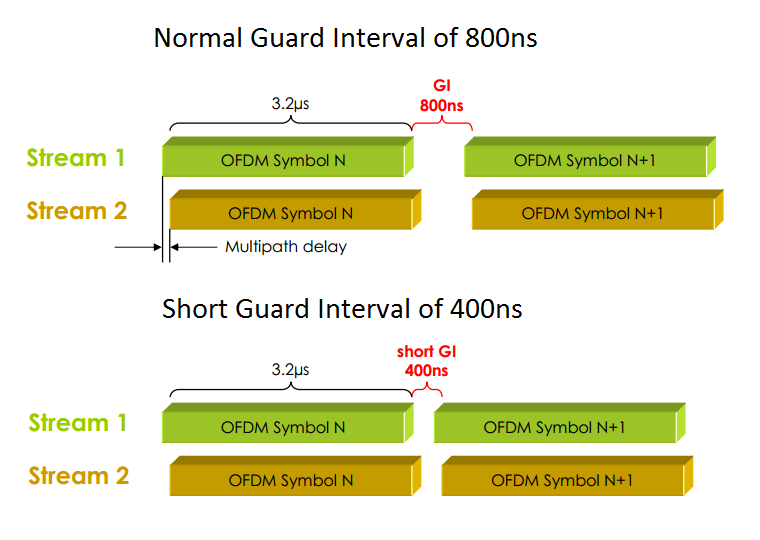
Shorter Guard Interval (GI)
In 802.11a, g and n, a symbol is transmitted every 4 microseconds. The improvement is realized on the Guard Interval (GI) duration. While 802.11a and g used an 800 nanoseconds GI, offering 3.2 microseconds for every symbol duration, 802.11n reduces this GI to 400 nanoseconds, allowing the symbol to persist during 3.6 microseconds. This slightly increases the maximum data rates. If we take the example of a transmission using 40MHz channels, the use of short GI improves the data rates of 150 Mbps per transmitter antenna.